
resistor box mis-install... could use some help
 12-20-2003, 11:49 AM
#1
Honda-Tech Member
Thread Starter
Join Date: Nov 2001
Location: out shooting
Posts: 2,800
Likes: 0
Received 0 Likes
on
0 Posts
hey guys, well in the heat of the moment i messed up installing my resistor box...i think. I used this picture and didn't check the actual wires to see if they went to the injcetors and now it is whining up and down at around 1500-2000 if it even kicks over at all ( have to give it gas ). skip the 'yer a tard' talk and help me out.

WHAT I AM ASKING is where do each one of these 7 wires going. there are 7 wires on my harness (for my 1992 integra gsr...obd1) and i used the rightest four wires... obviously thats wrong. i checked hondata's site and just got more confused. What i need to do now is rewire the wires which aren't the injectors back to stock, and the injector wires to the box. so if anyone has done any research and knows exactly where these 7 wires go, it would greatly help me out. Thanks.
credits to ladysman for the pic...
this doesn't help, but here is where i stand as of now...

once again, thanks for your help. seeya.
WHAT I AM ASKING is where do each one of these 7 wires going. there are 7 wires on my harness (for my 1992 integra gsr...obd1) and i used the rightest four wires... obviously thats wrong. i checked hondata's site and just got more confused. What i need to do now is rewire the wires which aren't the injectors back to stock, and the injector wires to the box. so if anyone has done any research and knows exactly where these 7 wires go, it would greatly help me out. Thanks.
credits to ladysman for the pic...
this doesn't help, but here is where i stand as of now...
once again, thanks for your help. seeya.
 12-20-2003, 03:08 PM
#2
B A N N E D

Join Date: Apr 2003
Location: CA, USA
Posts: 1,035
Likes: 0
Received 0 Likes
on
0 Posts
Here dan, hope this helps
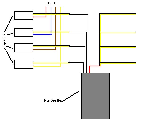
The resistor box has 4 black wires and one red wire. After cutting the black and yellow wires solder each of the black wires from the resistor box to each of the black and yellow wire that leads to the injectors, it does not matter which black wire in the resistor box goes to which injector. Be sure the black and yellow wires you find are actually the injector wires by checking for continuity on the injector connector. Now we need to connect the red wire from the resistor box to all 4 of the other black and yellow wires. It is best to use a butt connector to do this, if you try to solder all these wires together you will end up with a large ball of solder. See the wiring diagram below for using the resistor box.
The resistor box has 4 black wires and one red wire. After cutting the black and yellow wires solder each of the black wires from the resistor box to each of the black and yellow wire that leads to the injectors, it does not matter which black wire in the resistor box goes to which injector. Be sure the black and yellow wires you find are actually the injector wires by checking for continuity on the injector connector. Now we need to connect the red wire from the resistor box to all 4 of the other black and yellow wires. It is best to use a butt connector to do this, if you try to solder all these wires together you will end up with a large ball of solder. See the wiring diagram below for using the resistor box.
12-20-2003, 04:53 PM
#3
Junior Member
Join Date: Sep 2003
Location: Thiensville, WI
Posts: 490
Likes: 0
Received 0 Likes
on
0 Posts
you need to test for resistance in the wires. That's the only way you can find out unless you know someone with your model.
12-21-2003, 01:19 AM
#4
Junior Member
Join Date: Nov 2003
Location: Northern, NJ, USA
Posts: 306
Likes: 0
Received 0 Likes
on
0 Posts
gotta check for continuity to see which ones go to the injector.. the ones that have continuity and light up the meter, each one of those wires ( the ones from the injectors ) has to connect to its own black wire ( from the resistor box ) .. and then the remaining three wires ( the black and yellow ones that also come from the injector but dont have continuity ) all must be connected to the red wire ( from the resistor box )
12-21-2003, 08:48 PM
#5
Honda-Tech Member
Thread Starter
Join Date: Nov 2001
Location: out shooting
Posts: 2,800
Likes: 0
Received 0 Likes
on
0 Posts
thanks for your help guys...if you guys have any pictures or any more diagrams they couldnt hurt. im going to attemtp to fix what ive already screwed up.
12-21-2003, 10:00 PM
#6
Honda-Tech Member
12-21-2003, 10:07 PM
#7
New User
Join Date: Sep 2001
Location: NEVER FORGET
Posts: 1,158
Likes: 0
Received 0 Likes
on
0 Posts
you really only need to tap into one of the wires not all of them. they each have enough power for what needs to be done. no need to overload the circuit. that might lead to eld codes as well
Trending Topics
12-21-2003, 11:21 PM
#8
Junior Member
Join Date: Nov 2003
Location: Northern, NJ, USA
Posts: 306
Likes: 0
Received 0 Likes
on
0 Posts
just so no one gets confused and mis-installs it.. i think what Simple4012 means when he says you only need to tap into one of the wires, is that you only need to tap into one of the wires ( without continuity, this is the one that goes to the ecu ) to connect the red wire.. but each of the blacks need to be hooked up to its own injector wire which is black/yellow and has continuity..

Thread
Thread Starter
Forum
Replies
Last Post
Nextelbuddy
Forced Induction
5
06-12-2005 06:12 PM