
Complete DIY Plug and Play OBD2 Civic Resistor Box Write-up EJ6 EJ7 EJ8 EM1 EG1 EG2 EH6
 08-18-2007, 06:27 AM
#1
Junior Member
Thread Starter
Join Date: Mar 2006
Location: Duluth, MN
Posts: 201
Likes: 0
Received 0 Likes
on
0 Posts
I searched and read for quite some time looking for resistor box installation instructions for my EJ8 that wouldn’t require modification of the OEM wiring harness. I read that an OBD1 distributor harness would plug into the dead end harness, but soon found that this was not true because my dead end harness has 14 wires (14p), where the distributor harness that I had collected had only 8 wires (8p). Failing to find the information I needed here, I decided to create my first write-up.
Caution: Disconnect battery before doing anything!
We first must understand the function of the dead end plug. From what I understand, the dead end harness and plug work as a junction to provide power to various things while still leaving the option to add resistance if need be. Here is a photo of plug that goes into the dead end harness:
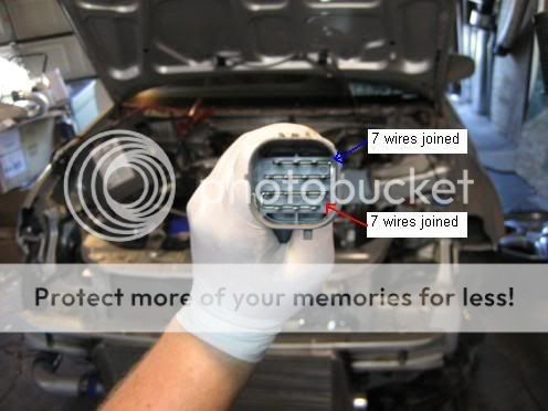
As you can see, there is one metal piece running through the plug to connect all the top 7 wires together, and another connecting all the bottom 7 together. The plug doesn’t connect all the wires together as does the 8p plug. The only instructions I found here said to find the 4 injector wires, connect those to the resistor box, and then connect all the remaining wires to the power wire for the resistor box. This WILL NOT work for the 14p dead end harness.
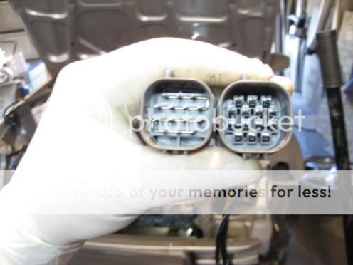
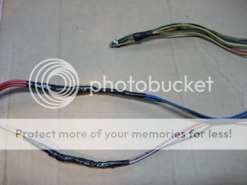
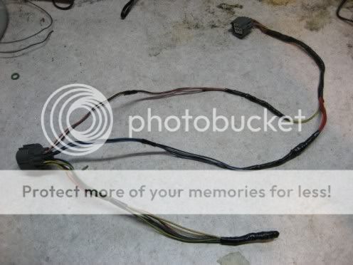
To completely avoid modifying the stock harness (including re-pin), I knew I would have to find a 14p harness that would fit into the dead end harness. Being that I have an EJ8 chassis, the engine harness is one piece, so I used my stock harness with my B18B engine swap. This left me with the extra B18 harness. I almost immediately found the plug I needed on one end of the B18 harness. There was a white plastic piece that I removed with needle nose pliers from inside the plug to make sure it would fit properly. I don’t have a picture of the engine harness it came from or the white piece I removed, but here are a couple pictures of the soon to be resistor box harness and the plug I removed from the dead end harness together:
If you are able to get a 14p harness like I did, make sure to cut as far down as possible to avoid needing to extend wires. If you are unable to get a 14p harness and will not be making a plug and play resistor box, then the instructions will be very similar, but look at the end of this write-up for hard wiring the resistor box.
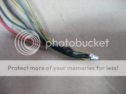
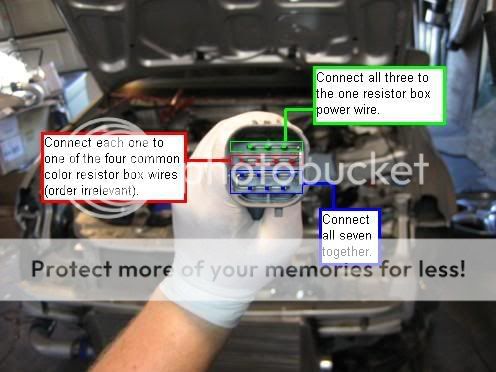
After removing the dead end plug, take the new 14p resistor box harness and plug it into the dead end harness (make sure the battery is disconnected). Now strip ends of the 14 wires for testing as well as soldering a little later. To find the injector wires, use a multimeter and check for continuity between the wires from the new harness and the injector clip terminals. Testing for continuity basically means to make sure one end of the wire is connected to the other and is able to conduct electricity. To do this, set the multimeter to check for continuity, which should be next to ohms. Next, look for the common color wire between all the injector clips. In my case it was yellow with a black line. To check for continuity, place one of the multimeter leads (doesn’t matter which one) on the common color injector terminal, and touch the other to each of the 14 wires individually until the meter shows continuity. Continue this process for all 4 injector clips and be sure to mark the wires as you find them. To speed up this process, you may want to try the four that I found first. Here is a photo of what I discovered:
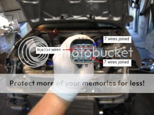
The wires were all in the second row for mine and it is very likely that yours are the same, but I cannot say for certain, so you must test for continuity.
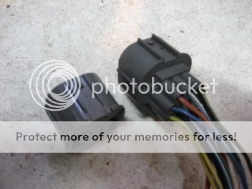
After locating the 4 injector wires, unplug the new harness and get the resistor box to begin soldering. Here is a picture of a resistor box (which can be found at almost any junkyard or on eBay):
I went to the junkyard for mine and made sure to get one with a complete plug and some length of wire left on it. This way I will be able to unplug my complete harness at any time, but leave the resistor box in place. Instructions are the same whether your resistor box has the plug or not.
The resistor box should have at least 4 common color wires coming out of it and one different color wire. I have heard of injector boxes having more than 4 common color wires, but only 4 will be used here. Solder the 4 injector wires you found on the new harness to the 4 common color wires on the resistor box and seal with heat shrink tubing (this is not required, but I believe it is the most reliable method of joining wires).
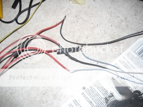
Now, recalling that the dead end plug only connected 7 wires at a time, find the other 3 wires that were connected by the dead end plug (besides the 4 injector wires), and solder those together with the different color resistor box wire as seen here:
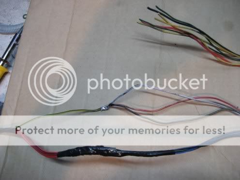
After sealing with heat shrink, take the remaining 7 wires and solder them together (they will not be connected to anything but each other):
Close up
Entire progess
Even after using heat shrink tubing, I still taped everything to be extra safe. I don’t need injectors failing.
Nearly finished
Finally, cover the harness with loom, zip-tie a few spots, and tape the ends. I chose to use ricey gray loom, with extra-ricey blue tape, but that’s the way I like it, so that’s the way I do it.
Finished harness

Hard Wiring the Resistor Box
I have not done this, but I would recommend removing your intake manifold for better access to the dead end harness. The process for finding the injector wires is the same, but rather than using an additional harness, the testing would be done using the female terminals on the dead end harness. Once you find which group of 7 wires the injectors are grouped with, pull all 7 of those pins from the plug, and replace the original dead end plug to keep the other 7 wires connected. Then, cut the pins off of the 7 wires that you removed and proceed with the instructions ignoring any reference to the other 7 wires.
Summary photo (for reference)
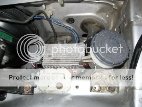
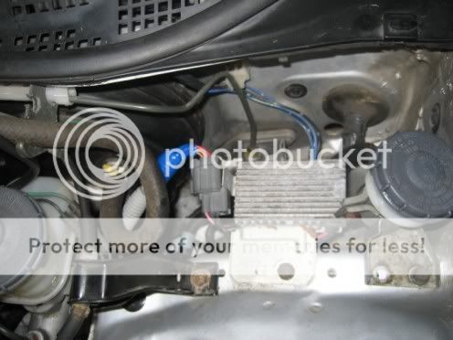
For the physical installation of the resistor box, I chose to relocate my harnesses on the driver side near the firewall to beneath the brake booster. Then, I moved the clutch fluid reservoir closer to the fender, and mounted the resistor box in its place. Here is how it looks installed:
Well, apparently I can’t wait for the fall semester of school to start because I am creating homework on my own. Hopefully this will at least help some people because I know when I looked at where my dead end harness was, I considered selling my injectors and getting some saturated ones. Now I can run either and also be prepared for much larger injectors. From what I’ve seen, 750cc is about as big as they get for saturated injectors.
Like previously stated, this is my first write-up, so it may have turned out very long, but I don’t think I included very much useless information. If you have suggestions on how I might improve this write-up, feel free to post here. Good luck!
Modified by DOWNwithHT at 11:48 AM 8/18/2007
Caution: Disconnect battery before doing anything!
We first must understand the function of the dead end plug. From what I understand, the dead end harness and plug work as a junction to provide power to various things while still leaving the option to add resistance if need be. Here is a photo of plug that goes into the dead end harness:
As you can see, there is one metal piece running through the plug to connect all the top 7 wires together, and another connecting all the bottom 7 together. The plug doesn’t connect all the wires together as does the 8p plug. The only instructions I found here said to find the 4 injector wires, connect those to the resistor box, and then connect all the remaining wires to the power wire for the resistor box. This WILL NOT work for the 14p dead end harness.
To completely avoid modifying the stock harness (including re-pin), I knew I would have to find a 14p harness that would fit into the dead end harness. Being that I have an EJ8 chassis, the engine harness is one piece, so I used my stock harness with my B18B engine swap. This left me with the extra B18 harness. I almost immediately found the plug I needed on one end of the B18 harness. There was a white plastic piece that I removed with needle nose pliers from inside the plug to make sure it would fit properly. I don’t have a picture of the engine harness it came from or the white piece I removed, but here are a couple pictures of the soon to be resistor box harness and the plug I removed from the dead end harness together:
If you are able to get a 14p harness like I did, make sure to cut as far down as possible to avoid needing to extend wires. If you are unable to get a 14p harness and will not be making a plug and play resistor box, then the instructions will be very similar, but look at the end of this write-up for hard wiring the resistor box.
After removing the dead end plug, take the new 14p resistor box harness and plug it into the dead end harness (make sure the battery is disconnected). Now strip ends of the 14 wires for testing as well as soldering a little later. To find the injector wires, use a multimeter and check for continuity between the wires from the new harness and the injector clip terminals. Testing for continuity basically means to make sure one end of the wire is connected to the other and is able to conduct electricity. To do this, set the multimeter to check for continuity, which should be next to ohms. Next, look for the common color wire between all the injector clips. In my case it was yellow with a black line. To check for continuity, place one of the multimeter leads (doesn’t matter which one) on the common color injector terminal, and touch the other to each of the 14 wires individually until the meter shows continuity. Continue this process for all 4 injector clips and be sure to mark the wires as you find them. To speed up this process, you may want to try the four that I found first. Here is a photo of what I discovered:
The wires were all in the second row for mine and it is very likely that yours are the same, but I cannot say for certain, so you must test for continuity.
After locating the 4 injector wires, unplug the new harness and get the resistor box to begin soldering. Here is a picture of a resistor box (which can be found at almost any junkyard or on eBay):
I went to the junkyard for mine and made sure to get one with a complete plug and some length of wire left on it. This way I will be able to unplug my complete harness at any time, but leave the resistor box in place. Instructions are the same whether your resistor box has the plug or not.
The resistor box should have at least 4 common color wires coming out of it and one different color wire. I have heard of injector boxes having more than 4 common color wires, but only 4 will be used here. Solder the 4 injector wires you found on the new harness to the 4 common color wires on the resistor box and seal with heat shrink tubing (this is not required, but I believe it is the most reliable method of joining wires).
Now, recalling that the dead end plug only connected 7 wires at a time, find the other 3 wires that were connected by the dead end plug (besides the 4 injector wires), and solder those together with the different color resistor box wire as seen here:
After sealing with heat shrink, take the remaining 7 wires and solder them together (they will not be connected to anything but each other):
Close up
Entire progess
Even after using heat shrink tubing, I still taped everything to be extra safe. I don’t need injectors failing.
Nearly finished
Finally, cover the harness with loom, zip-tie a few spots, and tape the ends. I chose to use ricey gray loom, with extra-ricey blue tape, but that’s the way I like it, so that’s the way I do it.
Finished harness
Hard Wiring the Resistor Box
I have not done this, but I would recommend removing your intake manifold for better access to the dead end harness. The process for finding the injector wires is the same, but rather than using an additional harness, the testing would be done using the female terminals on the dead end harness. Once you find which group of 7 wires the injectors are grouped with, pull all 7 of those pins from the plug, and replace the original dead end plug to keep the other 7 wires connected. Then, cut the pins off of the 7 wires that you removed and proceed with the instructions ignoring any reference to the other 7 wires.
Summary photo (for reference)
For the physical installation of the resistor box, I chose to relocate my harnesses on the driver side near the firewall to beneath the brake booster. Then, I moved the clutch fluid reservoir closer to the fender, and mounted the resistor box in its place. Here is how it looks installed:
Well, apparently I can’t wait for the fall semester of school to start because I am creating homework on my own. Hopefully this will at least help some people because I know when I looked at where my dead end harness was, I considered selling my injectors and getting some saturated ones. Now I can run either and also be prepared for much larger injectors. From what I’ve seen, 750cc is about as big as they get for saturated injectors.
Like previously stated, this is my first write-up, so it may have turned out very long, but I don’t think I included very much useless information. If you have suggestions on how I might improve this write-up, feel free to post here. Good luck!
Modified by DOWNwithHT at 11:48 AM 8/18/2007
 08-18-2007, 07:59 AM
#2
Honda-Tech Member
Join Date: Aug 2006
Location: VA
Posts: 888
Likes: 0
Received 0 Likes
on
0 Posts
From what I understood, all you had to do is splice the 4 wires. Then the one power wire for the resistor box could go to the wires on the engine harness and the 4 that were cut went to the resistor box. I could be wrong, but why did you do all that with that plug?
08-18-2007, 08:55 AM
#3
Junior Member
Thread Starter
Join Date: Mar 2006
Location: Duluth, MN
Posts: 201
Likes: 0
Received 0 Likes
on
0 Posts
<TABLE WIDTH="90%" CELLSPACING=0 CELLPADDING=0 ALIGN=CENTER><TR><TD>Quote, originally posted by madpipr »</TD></TR><TR><TD CLASS="quote">From what I understood, all you had to do is splice the 4 wires. Then the one power wire for the resistor box could go to the wires on the engine harness and the 4 that were cut went to the resistor box. I could be wrong, but why did you do all that with that plug?</TD></TR></TABLE>
I guess I'm not sure what you are asking. What do you mean by "all that"?
I guess I'm not sure what you are asking. What do you mean by "all that"?
08-18-2007, 09:20 AM
#4
Honda-Tech Member

Join Date: Sep 2005
Posts: 2,297
Likes: 0
Received 0 Likes
on
0 Posts
<TABLE WIDTH="90%" CELLSPACING=0 CELLPADDING=0 ALIGN=CENTER><TR><TD>Quote, originally posted by madpipr »</TD></TR><TR><TD CLASS="quote">I could be wrong, but why did you do all that with that plug?</TD></TR></TABLE>
To avoid having to splice into the wires.
Good writeup. Very thorough.
To avoid having to splice into the wires.
Good writeup. Very thorough.
08-18-2007, 09:30 AM
#5
Honda-Tech Member
Join Date: Aug 2006
Location: VA
Posts: 888
Likes: 0
Received 0 Likes
on
0 Posts
yes... i understand that he did it to make it cleaner and make it plug and play. but from what i have read, all you need to mess with is the 4 wires that have current. but i dont know why you are using all the wires on the plug. does that make sense?
08-18-2007, 10:07 AM
#6
Junior Member
Thread Starter
Join Date: Mar 2006
Location: Duluth, MN
Posts: 201
Likes: 0
Received 0 Likes
on
0 Posts
I think I understand what you are saying. The reason is because once the plug is removed from the dead end harness, there is nothing connecting the wires like there previously was. Look at the first picture, you will see that there is one piece of metal running through the plug connecting the top 7 terminals together and another connecting the bottom 7 terminals. When the plug is replaced with the new harness, the wires are no longer connected, so they must be soldered together in order for everything to work properly. Does that make sense?
08-18-2007, 04:35 PM
#7
Honda-Tech Member
Join Date: Aug 2006
Location: VA
Posts: 888
Likes: 0
Received 0 Likes
on
0 Posts
yeah... that makes sense now... i think... lol.... ive never been one to do a lot of wiring...
Trending Topics
08-22-2007, 06:36 PM
#10
Honda-Tech Member
Join Date: Apr 2004
Location: Vietnam
Posts: 282
Likes: 0
Received 0 Likes
on
0 Posts
Amazng write up. I been trying to find a thread to DIY for an OBDII but had no luck untill you made this thread. Finally my h22 swap will be done haha
08-22-2007, 08:51 PM
#11
Honda-Tech Member
Join Date: May 2007
Location: Gilroy, Ca, USA
Posts: 599
Likes: 0
Received 0 Likes
on
0 Posts
Similar to what I did, but I didn't mind splicing a connector for the resistor box into the harness, because it is just another plug added, which goes to the resistor box. I just got a second "dummy plug" and pulled the pins out that go to the injectors. So if you put in the origional one, the resistor box is bypassed, and if you plug in the other, it uses the resistors. 
08-23-2007, 08:04 AM
#12
Junior Member
Thread Starter
Join Date: Mar 2006
Location: Duluth, MN
Posts: 201
Likes: 0
Received 0 Likes
on
0 Posts
<TABLE WIDTH="90%" CELLSPACING=0 CELLPADDING=0 ALIGN=CENTER><TR><TD>Quote, originally posted by JaredKaragen »</TD></TR><TR><TD CLASS="quote">Similar to what I did, but I didn't mind splicing a connector for the resistor box into the harness, because it is just another plug added, which goes to the resistor box. I just got a second "dummy plug" and pulled the pins out that go to the injectors. So if you put in the origional one, the resistor box is bypassed, and if you plug in the other, it uses the resistors. </TD></TR></TABLE>
Yeah, the only problem is that it can be very difficult to work with that harness on OBD2 Civics when the engine is in the car. From the looks of your avatar, you have an OBD1 Civic, so this write-up really isn't necessary in your case.
</TD></TR></TABLE>Yeah, the only problem is that it can be very difficult to work with that harness on OBD2 Civics when the engine is in the car. From the looks of your avatar, you have an OBD1 Civic, so this write-up really isn't necessary in your case.

Thread
Thread Starter
Forum
Replies
Last Post
DOWNwithHT
Honda Civic / Del Sol (1992 - 2000)
36
12-13-2014 07:03 PM
Pancho2193
Honda Civic / Del Sol (1992 - 2000)
1
11-24-2012 10:02 PM
Rus1an
Forced Induction
8
05-18-2007 08:51 AM